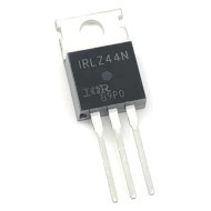
110N8F6 110A 80V 200W N-CHANNEL MOSFET
(0
reviews)
Inhouse product
Price
৳70.00
/1
Share
Top Selling Products

Reviews & Ratings
0
out of 5.0
(0
reviews)
There have been no reviews for this product yet.
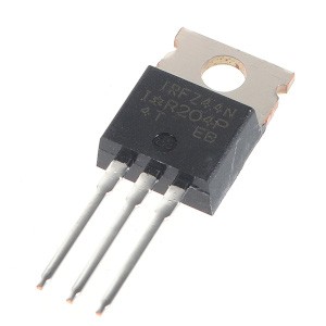
The 110N8 is an N-channel MOSFET (Metal-Oxide-Semiconductor Field-Effect Transistor) with a high current-handling capacity of 110A and a voltage rating of 80V. This type of MOSFET is typically used in applications such as motor drivers, power converters, and high-power switching circuits.
Key Specifications
| Parameter | Value |
|---|---|
| Maximum Drain Current (Iₐ) | 110A |
| Drain-Source Voltage (Vₓ) | 80V |
| Maximum Power Dissipation (Pₐ) | 200W |
| Gate Threshold Voltage (Vₐ) | Typically 2-4V |
| R<sub>DS(on)</sub> (On-State Resistance) | Very low (varies by model and Vgs) |
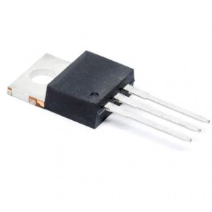
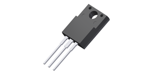
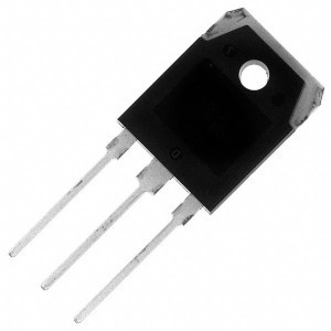
| Package | TO-220 or equivalent |
Features
- High Current and Voltage Capacity: Suitable for driving heavy loads.
- Low R<sub>DS(on)</sub>: Reduces conduction losses, making it efficient for power applications.
- Fast Switching: Suitable for high-frequency operation.
- Thermal Stability: Can handle significant power dissipation with appropriate heat sinking.
Applications
- Motor Drivers: Control of DC motors or stepper motors.
- Power Supplies: DC-DC converters, inverters, and switching regulators.
- LED Drivers: High-current LED arrays.
- Battery Management: In circuits requiring high current handling.
- Switching Circuits: For switching high-power loads efficiently.
Pin Configuration (Typical for TO-220 Package)
- Gate (G): Control input; a voltage here switches the MOSFET on or off.
- Drain (D): Connected to the load.
- Source (S): Connected to ground or the negative terminal.
How to Use in Circuits
Gate Control:
- Use a suitable gate driver or microcontroller to provide the gate voltage.
- A voltage above the gate threshold voltage (V<sub>gs(th)</sub>) is required to fully turn on the MOSFET.
- For logic-level operation, ensure the MOSFET can fully switch on at the voltage provided by your controller (e.g., 5V or 3.3V).
Drain-Source Circuit:
- Connect the load between the positive voltage source and the drain.
- Ensure the drain-source voltage and current ratings are not exceeded.
Gate Resistor:
- Include a small resistor (10-100Ω) between the control signal and the gate to limit inrush current and reduce ringing.
Protection Diode:
- For inductive loads, add a flyback diode across the load to protect the MOSFET from voltage spikes.
Heat Dissipation:
- Use a heat sink or active cooling to manage heat dissipation for high-power applications.
Frequently Bought Products
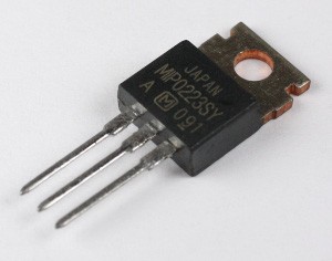
MIP0223SY P-CH Power Mosfet
৳100.00
Product Queries (0)
Login Or Registerto submit your questions to seller
Other Questions
No none asked to seller yet
Top Selling Products
Online Electronics Spears Shop in Bangladesh.